Introduction
The purpose of this document is to give a basic overview of the simulator, common questions and
demonstrate use of multiple simultaneous simulations with multiple simulators.
And fundamental high load testing plus the use of TCAP FSM and ISUP FSM simultaneously.
Frequently asked questions
Q: What is FSM and what is the difference between FSM and scripts?
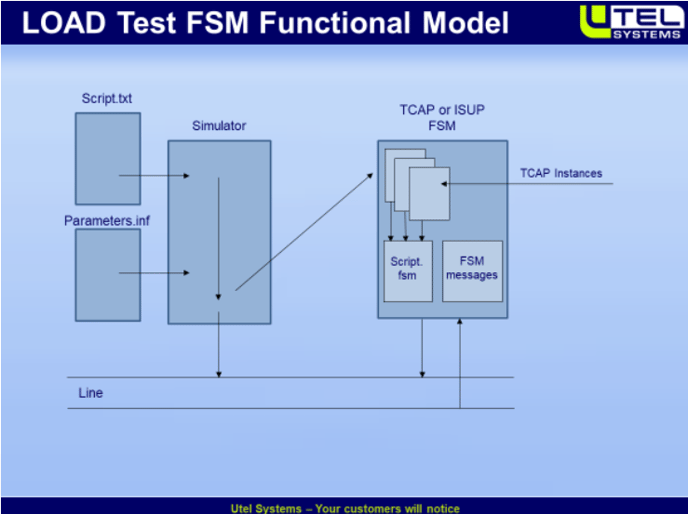
A: Answer: FSM (finite state machine) is code that handles TCAP, ISUP and IUP dialogs. Files with
extension fsm are scripts used by the TCAP FSM - while a script (with extension txt is script
used by the simulator. - see picture below for a functional view of the simulator functions:
Q:How to create an fsm script?
A: this can be done the same way as an ordinary script, but must be saved with extension
fsm. Any text editor can be used. Notepad is ok.
Q:What is Trigger and how to create and use?
A:A trigger is an event that trigger a specific action, it is a script command for the TCAP FSM.
(see examples in the Special Examples: Delayed Triggers and Delayed Triggers with Charging
Report both examples have a document in the doc directory that explain triggers)
Q:How to use Call Generator for TCAP?
A:The Call Generator for TCAP FSM loads the basic files for a test involving TCAP records. It can set the start time for a test, and it can synchronise multiple simulators. (an example is
demonstrated later in this file)
Q: What is the action needed to create a given flow of messages? (i.e. how to implement a test scenario)
A: We differentiate between functional testing and the use of FSM system. Functional testing can be done with a simple script using basic “tx” and “rx” commands, or it can be used in combination with auto answer. Auto answer is a file system that triggers specific script by a specified set condition (example can be seen in the Learning demo: MAP SMS MT).
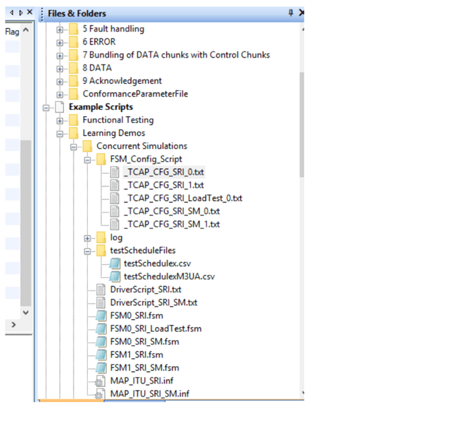
Use of the TCAP FSM system: The TCAP FSM system gives the possibility to filter out separate calls and provide load testing. All examples are build using the same directory template. See picture below.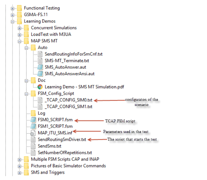
The picture above is taken from the Learning demo: MAP SMS MT, but any call flow should
be built with the same template as shown here. The basic components are : 1. The
_TCAP_CONFIG file that contains the loading of the required files and the commands to both
the simulator and the FSM system. The FSMO_SCRIPT.fsm is the script read by the FSM
system, the MAP_ITU_SMS.inf file (loaded from the config file) contains the parameters
needed in the test scenario. The SendRoutingSmDriver.txt is the script used by the simulator, it starts the test — i.e. at least send the first message. It is recommended to go through this
example.
The simulator contains a lot of examples that can be taken as a start point — find one that is close to
what you need and modify it to meet your requirements.
Q:How to check the TCAP Dialog timeout settings
A: The dialog FSM settings is reached from “Simulator->(fsm) State Machines->settings. See
picture below:
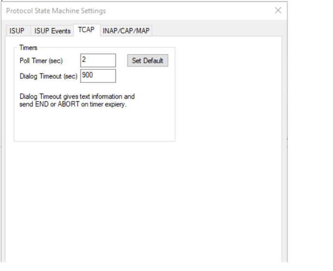
The values can be set into the dialog. You can also set the timer dialogs by commands
launched by a _TCAP_CFG script - see the file _TCAP_CFG_commands.txt. If you have a
scenario where no delays are required you can turn the poll timer off with the cmd: “set
polltimer tcap off”.
Q:How to make a scenario that is a load test over a long time?
A: This is achieved by using the TCAP fsm script to launch a new call when the TCAP fsm file
receives an TCAP END message for a call. See the file: FSMO_SRI_loadtest.fsm (in the current
example i.e. this example)
Q:What is the difference between TCAP FSM and ISUP FSM?
A: The ISUP FSM is a state machine that implement the rigid ISUP specification. While the
TCAP FSM is a flexible TCAP state machine that reads fsm script made by the user. The
flexibility of the TCAP FSM system makes it a tool for the higher layer protocols like MAP
CAMEL INAP (CS1 CS2 etc.) CS1+Alcatel, CS1+Ericsson and ASE-RI.
Q:Can TCAP FSM and ISUP FSM be used simultaneously?
A: Yes -and this can be used to provide scenarios that involves both TCAP and ISUP.
You need to route received messages to the ISUP and TCAP FSM modules. this is done by
turning the ISUP and FSM to ON. (an example is done later in this tutorial)
Q: What is Display Modes?
A: There are 3 different display modes. 1. The ordinary one picks up the messages from
ethernet. (that is below SCTP) 2. Monitor over SCTP — the messages are picked up above SCTP
— this reduces the load between the simulator agent and the simulator GUI since all the SCTP
acks not are forwarded to GUI. 3. Load test Display. With Load test display only information
about the traffic is sent to GUI - this is used with load tests that requires high call rate (since
a message is sent up to GUI for every 1000 calls there is s a substantial reduction in resources
used between GUI and agent which benefits the call rate possible.
Q: How do | set the range of numbers | can use in a test into an acronym containing the number.
A: This can be done with the simulator command: “set parameter msisdn22
18488744282:10;” where msisdn22 is the acronym 18488744282 the number and 10 the
range i.e. the last number will be 18488744292 before it raps around and use 18488744282
again. NOTE this only applies to numbers codes as BCD numbers and the command must be
combined by setting the byte offset to the first byte containing a BCD digit within the
parameter.(“set parameter offset msisdn22 3” - where 3 is the offset within the parameter
msisdn22 index 0 is the first byte in the parameter.
Q: how do | copy information from incoming messages?
A: you can store parts of the incoming message to internal message boxes by the simulator
command: “loadmsgbox <boxnr> <filter to specify the part you want>” here is an example:
“loadmsgbox 0 tcap 22|04|03|05;” will find the operation 22 within tcap the search for the
tag 04 then 03 is the byte offset with in the 04 parameter 05 is the number of bytes to copy
into the message box 0.(then the bytes in the box can be copied to any parameter by the
command “modifyinfoel <acronymname>|<byte offset within this acronym> <boxnr>;”
(modifyinfoel conRNR|4 0; will copy the content in message box 0 to the acronym cpnRNR
starting at bytenr 4 in the conRNR parameter.)
Q: How do | control the CIC values in a load test?
A: The CIC value range is set by the simulator command: cic <value>:<range>; i.e. cic 1:100;
will set the cic to 1 and the max cic number to 100.(if cic +1; is used somewhere in the setup, then when cic equals 100 it wraps back to 1.)
Demonstrated in This demo
- Use of multiple simulators
- Use of the new load display mode
- Setting number ranges for a test
Scenarios Description
We have picked out two scenarios for this demo:
1. Send Routing information
2. Send routing information for SM
3. SRI with TCAP and ISUP
The Basic scenario for both SRI and SRI_ForSM.
NOTE: the drawing is equal for send routing info (SRI) and send routing info for SM(SRISM)
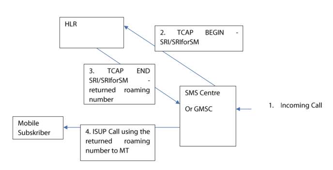
Signaling Scenario for SendRoutingForSM
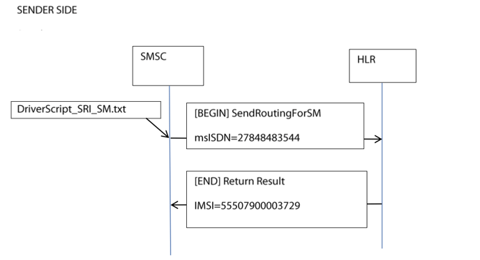
The scenario is basically the same for both simulations — but SRI is used for voice calls and SM for SMS sent from SMS service center to terminating mobile (MT)
The returned number from HLR are different:
For SRI it’s a msisdn number and for SRI for SM it’s an IMSI number to be used by VLR.
Using 4 simulators with the USB TDM box
Do the following:
- Start the simulator with standard ITU and user part SCCP. (make sure the loop cable is
connected between port 0 and 1) - Make a simulator in a timeslot (16), hook of loop and wait until you see FISU from both sides.
- Make a new simulator in another timeslot (17) again wait for FISU from both sides.
- Find the directory Learning demos\Concurrent simulations.
- Execute _TCAP_CFG_SRI_0.txt in simulator 0. _TAP_CFG SRI_1.txt in simulator 1.
_TCAP_CFG_SRI_SM_0.txt in simulator 2 and finally_TCAP_CFG_SRI_SM_1.txt in simulator3. - The configuration is now set up so simulator 0 can activate SRI calls simulator 1 will make
responses to SRI calls. Simulator 2 is set up to make send routing for SM calls and simulator
is set up for responding to send routing for SM calls. -note that the driver script have set repetitions to 20 calls and the time between calls to 2 seconds so he overall tests will last for
about 40 seconds. - Execute Driverscript_SRI.txt from simulator 0 - then switch to simulator 2 and execute
DriverScript_SRI_SM.txt. - By switching between the simulators, you can observe that testing goes on in all 4 windows.
Using the Call Generator Dialog to execute multiple tests.
In the latter example the _TCAP_CFG files was loaded manually script by script and this wasthe case also when starting driver scripts in simulator 1 and simulator 2. The call generator
manages multiple simulators in addition to synchronize scripts to start at a given time.
Do the following:
- Open the CallGen by clicking on the CallGen button.
- Load the testSchedules.csv (comma separated file, can be read by xl...) into the Dialog.
- Set the start and stop times (start time could be 2 min from current time and stop time more
than that...) - Set repetitions to 1.- this is set to 1 here so its easy to use the same scripts as we used when
loading manually. - Click ok.
Using two simulators with M3UA
Note the same scripts as used for the TDM can be used for all carrier protocols.
But for simplicity we will only use two m3ua simulators in the following.
Do the following:
- Use two pcs with the simulator application installed on both.
- Setup one pc as SGP and the other as ASP (server and client)
- Establish an association between the two — wait until you see that m3ua is established.
- Set up a new SGP on the SGP pc and a new ASP on the ASP pc use a different port number for the ASP side — establish a new M3UA connection between the two pcs (you should now have two windows on each pc i.e. two simulators on each pc.
- Use _TCAP_CFG_SRI_1.txt and -TCAP_CFG_SRI_SM_1.txt on the SGP pc —- and _TCAP_CFG_SRI_0.txt and __TCAP_SRI_SM_0.txt on the ASP pc
- Execute the two driver scripts from the ASP pc — DriverScript_SRI.txt in simulator 0 and DriverScript_SRI_SM.txt in simulator 1.
- The test should take about 40 secs ...so you have plenty of time to see that the two simulations are carried out simultaneously-...!
Call generator used with m3ua
Since the setup now includes only two simulators on each pc the file used by call generator dialog
are slightly changed.
Do the following.
- Click on callgen and load the file. \testschedule\testschedulem3ua.txt
- Choose stat time and set repetitions to 1.
- Click ok. 8 make sure to enable the simulators before you click ok 1
Load Test with M3UA
Considerations:
Normally the messages seen on the screen are collected at ethernet level, and sent from the simulator to the GUI. Choosing the monitor over SCTP. will decrease the load on the simulator agent and hence increase the load possible.
But still when the load is high a substantial part of the resources is used to forward messages from the simulator agent to the simulator GUI.
Choosing the mode “load Test Display” will remove the time spent to forward messages to GUI - and hence increase the load possible.
When this mode is on there is no messages sent up to GUI — instead information is set up for every 10.000 TCAP END message received — giving information about the call rate and the number of active calls. See picture below:
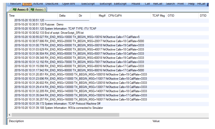
Do the following:
1. With the two active simulators — clear all windows in all windows.
2. On the SGP pc select monitor over SCTP
3. On the ASP PC select “load test Display”
4. Execute \FSM-Config_Script\_TCAP_CFG_SRI_Loadtest_0.txt
5. Open the Driver Script: Driverscript_SRI.txt and put # before the command: #pause 2000;
6. Activate the DriverScript_SRI.txt
7. Observe the result. it should be similar to the picture above.
SRI using TCAP FSM and ISUP FSM simultaneously
Do the following:
Setup two pcs as for the last example (with two pcs)
1. Activate M3UA
2. Execute the FSM_Config_Script: TCAP_CFG_SRI_With_ISUP_0.txt in simulator 0
3. Execute the FSM_Config_Script: TCAP_CFG_SRI_With_ISUP_1.txt in simulator 0
4. Execute the _ISUP_FSM_SHORTCALL_ON.txt script in simulator0. This will tell the ISUP FSM to release the call immediately when it reach active state(which is an advantage in order to provide a high call rate - and it eases the test..
5. Execute from simulator 0 the driver script: DriverScript_SRI_With_ISUP.txt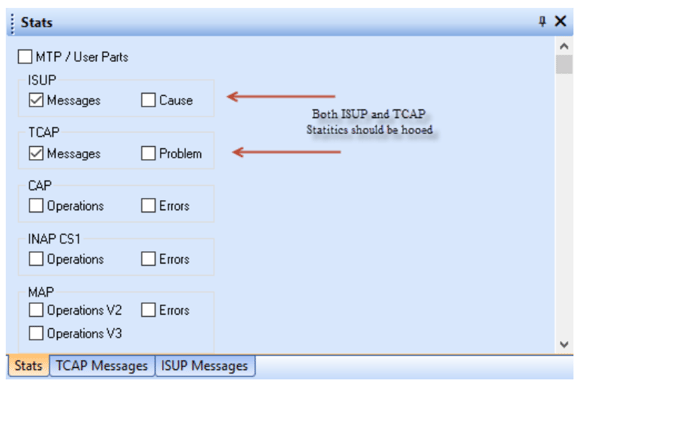
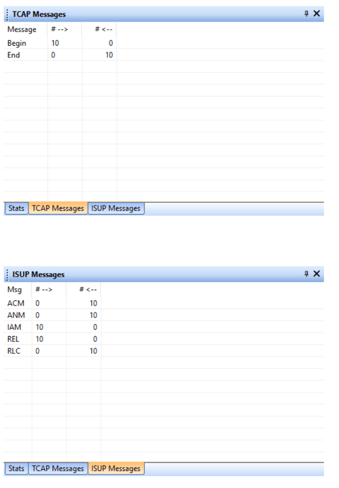
If the above is set before the test is run and the windows are cleared then the results can be viewed
in the respective stat panes:
Explanation of the 3 Important Files:
1. The configuration file: _TCAP_CFG_SRI_with_ISUP_0.txt
This file contains all the setting you need to carry out the test. It also provides the memory of the
settings when the same test is needed to be rerun sometime in the future.
#simcommand "clearmessagebuff";
load script ".\FSMO_SRI_withISUP.fsm"; <-------------------------------- Load the FSM script

#LOAD PARAMETERS INTO THE SIMULATOR

LOAD PARAMETERS ".\MAP_ITU_SRI.inf"; <-------------------------------- Load the parameters
simcommand "set userpart sccp"; <----------------------------- set the userpart to sccp
simcommand "set applicationProtocol map"; <------------------------- set the high layer application

#set numbers, numbers offset, and number ranges

simcommand "set parameter offset cpn 7";<---------------- set the BCD number offset to cpn acronym
simcommand "set parameter offset msisdn22 3"; G-set the BCD number offset to msisdn22 acronym
simcommand "set parameter cen 80061 1640:10"; <-set number and range for sccp cpn acronym

simcommand "set parameter msisdn22 18488744282:10";<-set number and range for MAP
msisdn22 acronym

simcommand "cic 3:100";<-set initial cic and the range to indicate when to apply round robin
principle.

simcommand "tcap_fsmon"; <-set the TCAP FSM to on
simcommand "isup_fsmon';<- set the ISUP FSM to on

simcommand “iup_fsmoff";<- make sure the IUP is set o off (the poll timer is turned off when the FSM is turned off)

scriptreadmode 1; <- always start reading the FSM sript from line 1 when a TCAP instance reads the FSMS script fter a message is received.
2. The FSM Script: FSMO_SRI_withISUP.fsm
#text "MAP SMS Demo"; <- for testing you can remove the # and the text should be displayed
#text "send Isup from this point",

set userpart sccp; <----------------------------------------- set user part to SCCP

set applicationProtocol map;<- set the high layer protocol to MAP

loadmsgbox 0 tcap 22|04|03|05;<-find tcap then find operation 22 and the tag=04 from offset 3
with in the parameter with tag 04 copy 5 bytes to message box 0.

set userpart isup; <- set userpart ISUP (need to find acronyms in this category)

modifyinfoel cpnRNR|4 0; <-in the ISUP acronym cpnRNR copy in the bytes from messagebox 0
Start at offset 4 in the cnRNR acronym

dpc 3; <- set the destination point code to be used for the next tx command.

ope 1; <- set the originating point code to be used for the next tx command.

tx x iam fnci ffci fcc ftmr vcpnRNR ocgn oeop;< message to be fed to the ISUP FSM
cic +1;<- prepare for the next cic to be used

set userpart sccp;<- reset the userpart back to SCCP

dpc 1;<-reset the dpc back to the values used by TCAP

opc 2;;<-reset the opc back to the values used by TCAP

rx udt;<- stop reading commands

stop;<- end
3. The Driver Script: DriverScript_SRI_With_ISUP.txt
#General Commands

text "File name: $.txt";


text" ;
text "Purpose: Demo";

#General Settings

itutcap; <- set itutcapformat

dpc 1;

opc 2;

set userpart sccp;

set applicationprotocol map;

pause 1000;

set tcapid origid:10203040;<- se the starting TCAP Id

#cic 26; <- possible to change the cic starting from the one set in the config file
#THE LOOP...

repeat 10; <- the loop is done 10 times i.e. 10 separate scenarios

operation 22 msisdn22 interType22 orCap22 gmscAddr22 callRefNum22 netSiginfo22 camInfo22;<-
the MAP operation SRI=22

invokeid 1;< set ROSE Invoke ID

set rosemessage invoke; < set ROSE message type to INVOKE

use tcapDialogPortion req_srfsm22; < - set the TCAP application value to be used
txtcap begin;<- set TCAP message to BEGIN

tx x udt fppcl vcpn vcgnNr vdatt;<- SEND THE SCCP MESSAGE

set tcapid origid: +1;<-set the next TCAP Id to be used

set parameter con +1;<-set the next SCCP cpn to be used

set parameter msisdn22 +1;<- set the next MAP msisdn22 acronym value to be used

pause 40;<- provides a deay between messages (windows requmend not lower than 20ms but that
depends on the scenario...)

endrepeat; <- end of loop — i.e. after 20 in this case we hit the text "End of script: $.txt";

text "End of script: $.txt";